The cutoff frequency of a filter is primarily determined by the application requirements, target signal frequency range, and filter performance specifications. It is generally calculated by considering several parameters, including the passband and stopband requirements, 3dB bandwidth, insertion loss, and out-of-band rejection. For RF filters, the cutoff frequency defines the boundary of the frequency range that can pass through the filter, making it an essential parameter for signal selection, interference suppression, and spectrum management.
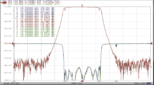
The cutoff frequency is not an arbitrary value. It is determined by several factors:
1. Application Frequency Range: The target operating frequency range is determined by the specific application. For example, a 2.4GHz Wi-Fi filter must allow signals within the target frequency band to pass while suppressing interference from other frequency bands.
2. Passband and Stopband Requirements: The passband is the frequency range within which signals are allowed to pass, while the stopband is the range in which signals need to be attenuated. The boundaries between these ranges help determine the cutoff frequency.
3. 3dB Bandwidth: The cutoff point is generally defined as the frequency at which the filter response drops by 3dB relative to its maximum passband level. For a bandpass filter, the 3dB bandwidth is the difference between the upper and lower cutoff frequencies.
4. Filter Design Parameters: The filter order, resonator structure, dielectric materials, circuit topology, and component values all influence the final cutoff frequency.
|
Filter Type
|
Cutoff Frequency Formula |
Main Function |
|
|
Low-pass filter |
fc = 1 / (2πRC)(RCcircuit) |
Allows low-frequency signals to pass |
|
|
High-pass filter |
fc = 1 / (2πRC)(RCcircuit) |
Allows high-frequency signals to pass |
|
|
Bandpass filter |
BW = fH − fL |
Allows signals within a specific frequency range to pass
|
|
|
Band-stop filter |
BW = fH − fL |
Suppresses signals within a specific frequency range |
Parameter description: fc is the cutoff frequency, fH is the upper cutoff frequency, fL is the lower cutoff frequency, BW is the bandwidth. For an ideal first-order RC low-pass or high pass circuit, the cutoff frequency is determined by the resistor R and capacitor C.
Consider an RF bandpass filter with a center frequency of 2.4GHz and a 3dB bandwidth of 100MHz.
The main parameters are:
Center frequency: 2.4GHz
3dB bandwidth: 100MHz
Lower cutoff frequency: 2.35GHz
Upper cutoff frequency: 2.45GHz
The calculation formulas are:
fL = f0 − BW / 2
fH = f0 + BW / 2
Therefore, the effective passband of this filter ranges from 2.35GHz to 2.45GHz. When the input signal frequency falls outside this range, the signal will gradually experience attenuation.
Q1: Does a higher cutoff frequency mean better filter performance?
A: Not necessarily. The cutoff frequency primarily determines the frequency boundary of a filter and does not directly indicate its overall performance. Other parameters, such as insertion loss, out-of-band rejection, bandwidth, and selectivity, must also be considered.
Q2: What is the difference between cutoff frequency and center frequency?
A: The center frequency represents the midpoint of a bandpass filter's passband, while the cutoff frequencies define the upper and lower boundaries of that passband. For a symmetrical bandpass filter, the center frequency is generally the arithmetic mean of the upper and lower cutoff frequencies.
Q3: Can the cutoff frequency be adjusted by changing component values?
A: Yes. For LC filters, the resonant frequency can be adjusted by changing the inductance and capacitance. For RF filters manufactured using LTCC or thin-film technologies, the cutoff frequency can be optimized by modifying internal electrode structures, resonator dimensions, and dielectric material properties.
Determining the cutoff frequency of a filter essentially involves designing the frequency boundaries according to the target signal range and system performance requirements. In practical applications, parameters such as center frequency, 3dB bandwidth, insertion loss, and out-of-band rejection must be considered together to ensure that the filter meets the requirements of different communication systems.
Yun Micro, as the professional manufacturer of rf passive components, can offer the cavity filters up 40GHz,which include band pass filter, low pass filter, high pass filter, band stop filter.
Welcome to contact us: liyong@blmicrowave.com


adres : Xisan Road, Mechanical and Electrical Industrial Park, No.767 Yulan Road, Hefei,Anhui.
tel : +86-18855146875
e-posta : liyong@blmicrowave.com


tara


